Blynk
Besonderheiten des Sparkfun-Blynk-ESP8266
BlynkTimer
DeepSleep
low-power operation DeepSleep
Setup
Configuration von Arduino und Blynk
- Installiere das die neuste Arduino-Software
- Schließe das SparkFun-Blynk-Board via USB-Kabel an den Computer an
- Füge das SparkFun Blynk Board zu Arduino hinzu
- Kopiere diese URL: http://arduino.esp8266.com/stable/package_esp8266com_index.json
- Füge die URL unter Arduino / Preferences / Additionel Bords Manager URLs ein
- Wähle unter Tools / Boards / Boardmanager
- Suche nach esp8266
- Installiere esp8266 — by ESP8266 Community
- Jetzt kannst Du unter Tools / Board / ESP8266 Boards / SparkFun Blynk Board anwählen
- Wähle unter Tools / Port / usbserial-.... an
- Falls unter Windows kein Port verfügbar ist, muss der FTDI-Treiber installiert werden — FTDI-Treiber-Download
- Danauch die Arduino-Software neu starten (evt. das Windows neu starten)
- Lade die Libraries aus dieser ZIP-Datei herunter
- Kopiere die Lybrarie in den Arduino-Libraries-Folder unter Documents / Arduino / Libraries
- [Arduino Big-Sur (Mac OS 11.01) Bug Workaround]
- Installiere die Blynk-App auf deinem Smartphone
- Eröffne dein eigenes Blynk-Konto
Benutzung
- Starte am Handy ein Projekt, indem Du in der Blynk-App ein neues Projekt erstellst
- Dir wird automatisch eine E-Mail mit dem App-Token zugeschickt
- Öffne die E-Mail am Computer und kopiere den Token
- Öffne einen Beispiel-Code in der Arduino-Software
- Füge in den Code den Token ein — "YourAuthToken"
- Füge in den Code die Zugangsdaten zu deinem WLAN ein "YourNetworkName" und "YourPassword"
- Lade den Code auf das Blynk-Board
- Nach dem automatischen Neustart des Boards kann die Blynk-App gestartet werden und sollte nun in Verbindung mit dem Board funktionieren
Examples für die Onboard-Bauteile
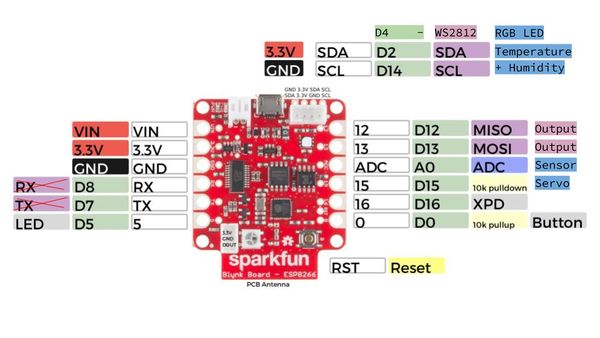
Das SparkFun-Blynk-Board ist bereits mit einigen interessanten Bauteilen wie Sensoren und LEDs bestückt, die leider kaum dokumentiert sind. (Der Blynk-Example-Code-Builder ist leider nicht mehr aktuell.) Daher demonstrieren diese Beispiele, wie die Onboard-Bauteile angesteuert werden können.
Sparkfun-Blynk-ESP8266 Onboard-LED
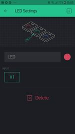
Auf dem Sparkfun-Blynk-ESP8266 Board befindet sich ein LED, der sich gut dazu eignet, um zum Beispiel den aktuellen Zustand eines Ausgangs darzustellen. Diese LED ist mit Pin 5 verdrahtet und kann auch darüber in der App angesteuert werden. Da die digitealen Pins (GP5) von der Blynk-Library automatisch geschlatet werden ist kein zusätzlicher Code nötig.
Onboard-LED
- Board: Sparkfun-Blynk-ESP8266
- Onboard-LED (eine ganz normale LED)
- Pin: 5
- Example-Blynk-App-Settings (siehe unten)
- Example-Code (siehe unten)
// Sparkfun-Blynk-ESP8266 Onboard-LED Example

/* Comment this out to disable prints and save space */
#define BLYNK_PRINT Serial

#include <ESP8266WiFi.h>
#include <BlynkSimpleEsp8266.h>

// You should get Auth Token in the Blynk App.
// Go to the Project Settings (nut icon).
char auth[] = "YourAuthToken";

// Your WiFi credentials.
// Set password to "" for open networks.
char ssid[] = "YourNetworkName";
char pass[] = "YourPassword";

void setup()
{
  // Debug console
  Serial.begin(9600);

  Blynk.begin(auth, ssid, pass);
}

void loop()
{
  Blynk.run();
  // You can inject your own code or combine it with other sketches.
  // Check other examples on how to communicate with Blynk. Remember
  // to avoid delay() function!
}
Sparkfun-Blynk-ESP8266 Read Onboard-Button
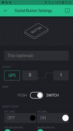
Auf dem Sparkfun-Blynk-ESP8266 Board befindet sich ein Taster, der sich gut dazu eignet, um zum Beispiel den aktuellen Zustand einer Tür (Reed-Schalter) in der App sichtbar zu machen. Dieser Taster ist mit Pin 0 verdrahtet und kann ober einen virtuellen Pin gelesen werden.
Onboard-RGB-LED
- Board: Sparkfun-Blynk-ESP8266
- Onboard-Taster an Pin — kann auch über einen externen Taster zischen Pin 0 und GND geschaltet werden
- Example-Code (siehe unten)
- Example-Blynk-App-Settings (siehe unten)
// Sparkfun-Blynk-ESP8266 Read Onboard-Button Example

/* Comment this out to disable prints and save space */
#define BLYNK_PRINT Serial

#include <ESP8266WiFi.h>
#include <BlynkSimpleEsp8266.h>

// You should get Auth Token in the Blynk App.
// Go to the Project Settings (nut icon).
char auth[] = "YourAuthToken";

// Your WiFi credentials.
// Set password to "" for open networks.
char ssid[] = "YourNetworkName";
char pass[] = "YourPassword";

#define ButtonPin 0

int prevState = -1;
int currState = -1;
long lastChangeTime = 0;

void checkPin()
{
  // Invert state, since button is "Active LOW"
  // int state = !digitalRead(ButtonPin);
  boolean state = !digitalRead(ButtonPin);

  // Debounce mechanism
  long t = millis();
  if (state != prevState) {
    lastChangeTime = t;
  }
  if (t - lastChangeTime > 50) {
    if (state != currState) {
      currState = state;
      if (state == 0) {
        Blynk.virtualWrite(V1, 0);
        Serial.println("Button Off");
      }
      if (state == 1) {
        Blynk.virtualWrite(V1, 1023);
        Serial.println("Button On");
      }
    }
  }
  prevState = state;
}

void setup()
{
  // Debug console
  Serial.begin(9600);

  Blynk.begin(auth, ssid, pass);

  // Make ButtonPin default HIGH, and attach INT to our handler
  pinMode(ButtonPin, INPUT_PULLUP);
}

void loop()
{
  Blynk.run();
  checkPin();
}
Sparkfun-Blynk-ESP8266 Onboard-NeoPixel
Auf dem Sparkfun-Blynk-ESP8266 Board befindet sich eine RGB LED, die sich sehr gut dazu eignet, um zum Beispiel einen aktuellen Zustand anzuzeigen. Diese RGB LED vom Type WS2812 ist mit Pin 4 verdrahtet und kann über die Library Adafruit_NeoPixel.h angesteuert werden.
Onboard-RGB-LED
- Board: Sparkfun-Blynk-ESP8266
- LED-Type: WS2812
- Library: Adafruit_NeoPixel.h
- Pin: 4
- Example-Code (siehe unten)
- Example-Blynk-App-Settings (siehe unten)
// Sparkfun-Blynk-ESP8266 Onboard-NeoPixel Example

#define BLYNK_PRINT Serial
#include <ESP8266WiFi.h>
#include <BlynkSimpleEsp8266.h>
#include <Adafruit_NeoPixel.h>

// You should get Auth Token in the Blynk App.
// Go to the Project Settings (nut icon).
char auth[] = "YourAuthToken";

// Your WiFi credentials.
// Set password to "" for open networks.
char ssid[] = "YourNetworkName";
char pass[] = "YourPassword";

#define PIN 4
int stripR = 0;
int stripG = 0;
int stripB = 0;
int stripL = 0;

Adafruit_NeoPixel strip = Adafruit_NeoPixel(1, PIN, NEO_GRB + NEO_KHZ800);

BLYNK_WRITE(V1)
{
  stripR = param[0].asInt();
  stripG = param[1].asInt();
  stripB = param[2].asInt();
  showRGB();
}

BLYNK_WRITE(V2)
{
  stripL = 255 - param.asInt();
  showRGB();
}

void showRGB() {
  int r = stripR - stripL;
  if (r < 0) r = 0;
  int g = stripG - stripL;
  if (g < 0) g = 0;
  int b = stripB - stripL;
  if (b < 0) b = 0;

  strip.setPixelColor(0, strip.Color(r, g, b));
  strip.show();
}

void setup()
{
  // Debug console
  Serial.begin(9600);
  Blynk.begin(auth, ssid, pass);

  strip.begin();
  strip.show();
}

void loop()
{
  Blynk.run();
}
Sparkfun-Blynk-ESP8266 Onboard-Temp-Humidity Senor
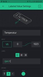
Auf dem Sparkfun-Blynk-ESP8266 Board befindet sich eine Temperatur- und Feuchtigkeitssensor, der sich sehr gut dazu eignet, um zum Beispiel das Raumklima zu erfassen. Diese I2C Sensor vom Type Si7021 ist mit Pin 2 und Pin 14 verdrahtet und kann über die Library SparkFun_Si7021_Breakout_Library.h ausgelesen werden.
Onboard Temperature and Humidity Sensor
- Board: Sparkfun-Blynk-ESP8266
- Sensor-Type: Si7021
- Library: SparkFun_Si7021_Breakout_Library.h
- Pin: 2 & 14 (werden von der Library automatisch gesetzt)
- Example-Code (siehe unten)
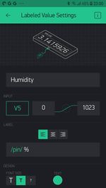
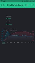
- Example-Blynk-App-Settings (siehe unten)
// Sparkfun-Blynk-ESP8266_Onboard-TempHumidity_Example

/* Comment this out to disable prints and save space */
#define BLYNK_PRINT Serial

#include <ESP8266WiFi.h>
#include <BlynkSimpleEsp8266.h>
// #include <DHT.h>
#include "SparkFun_Si7021_Breakout_Library.h"
#include <Wire.h>

// You should get Auth Token in the Blynk App.
// Go to the Project Settings (nut icon).
char auth[] = "YourAuthToken";

// Your WiFi credentials.
// Set password to "" for open networks.
char ssid[] = "YourNetworkName";
char pass[] = "YourPassword";

float humidity = 0;
float tempf = 0;
float tempc = 0;

//Create Instance of HTU21D or SI7021 temp and humidity sensor and MPL3115A2 barrometric sensor
Weather sensor;

BlynkTimer timer;

// This function sends Arduino's up time every second to Virtual Pin (5).
// In the app, Widget's reading frequency should be set to PUSH. This means
// that you define how often to send data to Blynk App.
void sendSensor()
{
  getWeather();
  printInfo();
  sendValues();
}

void setup()
{
  // Debug console
  Serial.begin(9600);

  Blynk.begin(auth, ssid, pass);
  // You can also specify server:
  //Blynk.begin(auth, ssid, pass, "blynk-cloud.com", 80);
  //Blynk.begin(auth, ssid, pass, IPAddress(192,168,1,100), 8080);

  //Initialize the I2C sensors and ping them
  sensor.begin();

  // Setup a function to be called every second
  timer.setInterval(1000L, sendSensor);
}

void loop()
{
  Blynk.run();
  timer.run();
}

//---------------------------------------------------------------
void getWeather()
{
  // Measure Relative Humidity from the HTU21D or Si7021
  humidity = sensor.getRH();

  // Measure Temperature from the HTU21D or Si7021
  // tempf = sensor.getTempF();
  tempc = sensor.getTemp();
  // Temperature is measured every time RH is requested.
  // It is faster, therefore, to read it from previous RH
  // measurement with getTemp() instead with readTemp()
}
//---------------------------------------------------------------
void printInfo()
{
  //This function prints the weather data out to the default Serial Port

  Serial.print("Temp:");
  Serial.print(tempc);
  Serial.print("°C, ");

  Serial.print("Humidity:");
  Serial.print(humidity);
  Serial.println("%");
}

void sendValues() {
  // You can send any value at any time.
  // Please don't send more that 10 values per second.
  Blynk.virtualWrite(V5, humidity);
  Blynk.virtualWrite(V6, tempc);
}
