Difference between revisions of "Blynk"
(→Sparkfun-Blynk-ESP8266 onboard-Temp-Humidity) |
|||
| (52 intermediate revisions by the same user not shown) | |||
| Line 1: | Line 1: | ||
| − | [[File:Blynk- | + | [[File:Sparkfun-Blynk-ESP8266-pins-map.jpg|600px]] |
| − | + | ''Die Blynk Plattform erlaubt es schnelle und einfach das Arduinos mit dem Handy zu steuern oder Daten von Sensoren auf dem Handy darzustellen.'' | |
| − | + | * '''Blynk-App''' — Mit dieser App kann mit fertigen Modulen, wie mit Lego-Bausteinen im Handyumdrehen eine Anwendung erstellt werden. Via Link und QR-Code kann die Anwendung dann veröffentlicht werden | |
| − | + | * '''Blynk-Server''' — Dieser läuft im Hintergrund des Blynk-Systems und macht den Datenaustausch erst möglich. Gelegentlich fordert die Blynk-App dazu auf, sich an den Server-Kosten zu beteiligen, indem eine sogenannte "Batterie" mit kleinen Beträgen (3 €) aufgeladen werden soll. Blynk bietet auch eine Anleitung zum Aufsetzten eines eigenen Servers. | |
| − | + | * '''Sparkfun-Board''' — Die Blynk-Plattform arbeitet mit einer ganzen Reihe von Arduino-Boards. Eine Liste der kompatiblen Hardware findest Du hier LINK. Das Sparkfun Blynk-ESP8266-Board wurde als kompaktes Bauteil mit WLAN und Akku speziell für Blynk-Projekte konzipiert. Zudem verfügt es über einen Temperatur- und Feuchtigkeitssensor so wie eine RGB-LED und Schnittstellen zu NeoPixel-WS2812-LEDs und I2C-Bauteilen. | |
| − | + | ||
| − | + | ||
| − | + | ||
| − | + | ||
| − | [https:// | + | <br> |
| + | |||
| + | = Setup = | ||
| + | |||
| + | <br> | ||
| + | |||
| + | == Configuration von Arduino und Blynk == | ||
| + | |||
| + | # Installiere das die neuste [https://www.arduino.cc/en/software Arduino-Software] | ||
| + | # Schließe das SparkFun-Blynk-Board via USB-Kabel an den Computer an | ||
| + | # Füge das SparkFun Blynk Board zu Arduino hinzu | ||
| + | #* Kopiere diese URL: http://arduino.esp8266.com/stable/package_esp8266com_index.json | ||
| + | #* Füge die URL unter '''Arduino / Preferences / Additionel Bords Manager URLs''' ein | ||
| + | #* Wähle unter '''Tools / Boards / Boardmanager''' | ||
| + | #* Suche nach '''esp8266''' | ||
| + | #* Installiere '''esp8266 — by ESP8266 Community''' | ||
| + | # Jetzt kannst Du unter '''Tools / Board / ESP8266 Boards / SparkFun Blynk Board''' anwählen | ||
| + | # Wähle unter '''Tools / Port / usbserial-....''' an | ||
| + | #* Falls unter Windows kein Port verfügbar ist, muss der FTDI-Treiber installiert werden — [https://cdn.sparkfun.com/assets/learn_tutorials/7/4/CDM21228_Setup.exe FTDI-Treiber-Download] | ||
| + | #* Danauch die Arduino-Software neu starten (evt. das Windows neu starten) | ||
| + | # Lade die Libraries aus dieser [[Media:Libraries.zip|ZIP-Datei]] herunter | ||
| + | # Kopiere die Lybrarie in den Arduino-Libraries-Folder unter '''Documents / Arduino / Libraries''' | ||
| + | # [Arduino Big-Sur (Mac OS 11.01) Bug [[Arduino Big-Sur Workaround|Workaround]]] | ||
| + | # Installiere die Blynk-App auf deinem Smartphone | ||
| + | # Eröffne dein eigenes Blynk-Konto | ||
| + | |||
| + | <br> | ||
| + | |||
| + | == Benutzung == | ||
| + | |||
| + | # Starte am Handy ein Projekt, indem Du in der Blynk-App ein neues Projekt erstellst | ||
| + | # Dir wird automatisch eine E-Mail mit dem App-Token zugeschickt | ||
| + | # Öffne die E-Mail am Computer und kopiere den Token | ||
| + | # Öffne einen Beispiel-Code in der Arduino-Software | ||
| + | # Füge in den Code den Token ein — '''"YourAuthToken"''' | ||
| + | # Füge in den Code die Zugangsdaten zu deinem WLAN ein '''"YourNetworkName"''' und '''"YourPassword"''' | ||
| + | # Lade den Code auf das Blynk-Board | ||
| + | # Nach dem automatischen Neustart des Boards kann die Blynk-App gestartet werden und sollte nun in Verbindung mit dem Board funktionieren | ||
| + | |||
| + | <br> | ||
| + | |||
| + | = Examples für die Onboard-Bauteile = | ||
| + | |||
| + | Das SparkFun-Blynk-Board ist bereits mit einigen interessanten Bauteilen wie Sensoren und LEDs bestückt, die leider kaum dokumentiert sind. (Der Blynk-Example-Code-Builder ist leider nicht mehr aktuell.) Daher demonstrieren diese Beispiele, wie die Onboard-Bauteile angesteuert werden können. | ||
| + | |||
| + | <br> | ||
| + | |||
| + | == Sparkfun-Blynk-ESP8266 Onboard-LED == | ||
| + | |||
| + | Auf dem Sparkfun-Blynk-ESP8266 Board befindet sich ein LED, der sich gut dazu eignet, um zum Beispiel den aktuellen Zustand eines Ausgangs darzustellen. Diese LED ist mit '''Pin 5''' verdrahtet und kann auch darüber in der App angesteuert werden. Da die digitealen Pins (GP5) von der Blynk-Library automatisch geschlatet werden ist kein zusätzlicher Code nötig. | ||
| + | |||
| + | |||
| + | '''Onboard-LED''' | ||
| + | * Board: [https://www.sparkfun.com/products/13794 Sparkfun-Blynk-ESP8266] | ||
| + | * Onboard-LED (eine ganz normale LED) | ||
| + | * Pin: 5 | ||
| + | * Example-Blynk-App-Settings (siehe unten) | ||
| + | * Example-Code (siehe unten) | ||
| + | |||
| + | |||
| + | [[File:Sparkfun-Blynk-ESP8266-onboard-led.jpg|150px]] | ||
| + | |||
| + | <pre> | ||
| + | |||
| + | // Sparkfun-Blynk-ESP8266 Onboard-LED Example | ||
| + | |||
| + | /* Comment this out to disable prints and save space */ | ||
| + | #define BLYNK_PRINT Serial | ||
| + | |||
| + | #include <ESP8266WiFi.h> | ||
| + | #include <BlynkSimpleEsp8266.h> | ||
| + | |||
| + | // You should get Auth Token in the Blynk App. | ||
| + | // Go to the Project Settings (nut icon). | ||
| + | char auth[] = "YourAuthToken"; | ||
| + | |||
| + | // Your WiFi credentials. | ||
| + | // Set password to "" for open networks. | ||
| + | char ssid[] = "YourNetworkName"; | ||
| + | char pass[] = "YourPassword"; | ||
| + | |||
| + | void setup() | ||
| + | { | ||
| + | // Debug console | ||
| + | Serial.begin(9600); | ||
| + | |||
| + | Blynk.begin(auth, ssid, pass); | ||
| + | } | ||
| + | |||
| + | void loop() | ||
| + | { | ||
| + | Blynk.run(); | ||
| + | // You can inject your own code or combine it with other sketches. | ||
| + | // Check other examples on how to communicate with Blynk. Remember | ||
| + | // to avoid delay() function! | ||
| + | } | ||
| + | </pre> | ||
| + | |||
| + | <br> | ||
| + | |||
| + | == Sparkfun-Blynk-ESP8266 Read Onboard-Button == | ||
| + | |||
| + | Auf dem Sparkfun-Blynk-ESP8266 Board befindet sich ein Taster, der sich gut dazu eignet, um zum Beispiel den aktuellen Zustand einer Tür (Reed-Schalter) in der App sichtbar zu machen. Dieser Taster ist mit '''Pin 0''' verdrahtet und kann ober einen virtuellen Pin gelesen werden. | ||
| + | |||
| + | |||
| + | '''Onboard-RGB-LED''' | ||
| + | * Board: [https://www.sparkfun.com/products/13794 Sparkfun-Blynk-ESP8266] | ||
| + | * Onboard-Taster an Pin — kann auch über einen externen Taster zischen Pin 0 und GND geschaltet werden | ||
| + | * Example-Code (siehe unten) | ||
| + | * Example-Blynk-App-Settings (siehe unten) | ||
| + | |||
| + | |||
| + | [[File:Sparkfun-Blynk-ESP8266-LED-Widget-Onboard-Button.jpg|150px]] | ||
| + | [[File:Sparkfun-Blynk-ESP8266-Read-Onboard-Button.jpg|150px]] | ||
| + | |||
| + | <pre> | ||
| + | |||
| + | // Sparkfun-Blynk-ESP8266 Read Onboard-Button Example | ||
| + | |||
| + | /* Comment this out to disable prints and save space */ | ||
| + | #define BLYNK_PRINT Serial | ||
| + | |||
| + | #include <ESP8266WiFi.h> | ||
| + | #include <BlynkSimpleEsp8266.h> | ||
| + | |||
| + | // You should get Auth Token in the Blynk App. | ||
| + | // Go to the Project Settings (nut icon). | ||
| + | char auth[] = "YourAuthToken"; | ||
| + | |||
| + | // Your WiFi credentials. | ||
| + | // Set password to "" for open networks. | ||
| + | char ssid[] = "YourNetworkName"; | ||
| + | char pass[] = "YourPassword"; | ||
| + | |||
| + | #define ButtonPin 0 | ||
| + | |||
| + | int prevState = -1; | ||
| + | int currState = -1; | ||
| + | long lastChangeTime = 0; | ||
| + | |||
| + | void checkPin() | ||
| + | { | ||
| + | // Invert state, since button is "Active LOW" | ||
| + | // int state = !digitalRead(ButtonPin); | ||
| + | boolean state = !digitalRead(ButtonPin); | ||
| + | |||
| + | // Debounce mechanism | ||
| + | long t = millis(); | ||
| + | if (state != prevState) { | ||
| + | lastChangeTime = t; | ||
| + | } | ||
| + | if (t - lastChangeTime > 50) { | ||
| + | if (state != currState) { | ||
| + | currState = state; | ||
| + | if (state == 0) { | ||
| + | Blynk.virtualWrite(V1, 0); | ||
| + | Serial.println("Button Off"); | ||
| + | } | ||
| + | if (state == 1) { | ||
| + | Blynk.virtualWrite(V1, 1023); | ||
| + | Serial.println("Button On"); | ||
| + | } | ||
| + | } | ||
| + | } | ||
| + | prevState = state; | ||
| + | } | ||
| + | |||
| + | void setup() | ||
| + | { | ||
| + | // Debug console | ||
| + | Serial.begin(9600); | ||
| + | |||
| + | Blynk.begin(auth, ssid, pass); | ||
| + | |||
| + | // Make ButtonPin default HIGH, and attach INT to our handler | ||
| + | pinMode(ButtonPin, INPUT_PULLUP); | ||
| + | } | ||
| + | |||
| + | void loop() | ||
| + | { | ||
| + | Blynk.run(); | ||
| + | checkPin(); | ||
| + | } | ||
| + | |||
| + | </pre> | ||
<br> | <br> | ||
| Line 18: | Line 198: | ||
== Sparkfun-Blynk-ESP8266 Onboard-NeoPixel == | == Sparkfun-Blynk-ESP8266 Onboard-NeoPixel == | ||
| − | Auf dem Sparkfun-Blynk-ESP8266 Board befindet sich eine RGB LED, die sich sehr gut dazu | + | Auf dem Sparkfun-Blynk-ESP8266 Board befindet sich eine RGB LED, die sich sehr gut dazu eignet, um zum Beispiel einen aktuellen Zustand anzuzeigen. Diese RGB LED vom Type '''WS2812''' ist mit '''Pin 4''' verdrahtet und kann über die Library '''Adafruit_NeoPixel.h''' angesteuert werden. |
| Line 104: | Line 284: | ||
<br> | <br> | ||
| − | == Sparkfun-Blynk-ESP8266 | + | == Sparkfun-Blynk-ESP8266 Onboard-Temp-Humidity Senor == |
| + | |||
| + | Auf dem Sparkfun-Blynk-ESP8266 Board befindet sich eine Temperatur- und Feuchtigkeitssensor, der sich sehr gut dazu eignet, um zum Beispiel das Raumklima zu erfassen. Diese I2C Sensor vom Type '''Si7021''' ist mit '''Pin 2 und Pin 14''' verdrahtet und kann über die Library '''SparkFun_Si7021_Breakout_Library.h''' ausgelesen werden. | ||
| + | |||
'''Onboard Temperature and Humidity Sensor''' | '''Onboard Temperature and Humidity Sensor''' | ||
* Board: [https://www.sparkfun.com/products/13794 Sparkfun-Blynk-ESP8266] | * Board: [https://www.sparkfun.com/products/13794 Sparkfun-Blynk-ESP8266] | ||
* Sensor-Type: [https://www.sparkfun.com/products/13763 Si7021] | * Sensor-Type: [https://www.sparkfun.com/products/13763 Si7021] | ||
| − | * Library: [https://github.com/sparkfun/SparkFun_Si701_Breakout_Arduino_Library | + | * Library: [https://github.com/sparkfun/SparkFun_Si701_Breakout_Arduino_Library SparkFun_Si7021_Breakout_Library.h] |
* Pin: 2 & 14 (werden von der Library automatisch gesetzt) | * Pin: 2 & 14 (werden von der Library automatisch gesetzt) | ||
* Example-Code (siehe unten) | * Example-Code (siehe unten) | ||
* Example-Blynk-App-Settings (siehe unten) | * Example-Blynk-App-Settings (siehe unten) | ||
| + | |||
| + | <br> | ||
| + | |||
| + | [[File:Sparkfun-Blynk-ESP8266 Onboard Temperature-Sensor.jpg|150px]] | ||
| + | [[File:Sparkfun-Blynk-ESP8266 Onboard Humidity-Sensor.jpg|150px]] | ||
| + | [[File:Sparkfun-Blynk-ESP8266 Onboard Temperature-Humidity-Sensor.jpg|150px]] | ||
<pre> | <pre> | ||
| Line 214: | Line 403: | ||
<br> | <br> | ||
| − | = | + | = Besonderheiten des Sparkfun-Blynk-ESP8266 = |
| + | |||
| + | <br> | ||
| + | |||
| + | == BlynkTimer == | ||
| + | |||
| + | [https://docs.blynk.cc/#blynk-firmware-blynktimer Example] | ||
| + | |||
| + | <br> | ||
| + | |||
| + | == DeepSleep == | ||
| + | |||
| + | low-power operation DeepSleep | ||
| + | |||
| + | [https://www.sparkfun.com/news/1842 LINK] | ||
| + | |||
| + | <br> | ||
| + | |||
| + | == Blynk + P5*JS == | ||
| − | . | + | [[P5*js#p5js_.26_Blynk|LINK]] |
<br> | <br> | ||
Latest revision as of 17:36, 14 February 2021
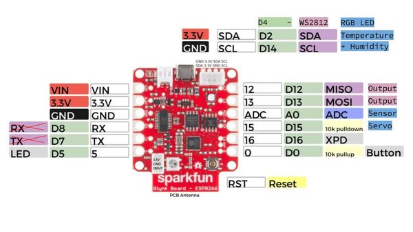
Die Blynk Plattform erlaubt es schnelle und einfach das Arduinos mit dem Handy zu steuern oder Daten von Sensoren auf dem Handy darzustellen.
- Blynk-App — Mit dieser App kann mit fertigen Modulen, wie mit Lego-Bausteinen im Handyumdrehen eine Anwendung erstellt werden. Via Link und QR-Code kann die Anwendung dann veröffentlicht werden
- Blynk-Server — Dieser läuft im Hintergrund des Blynk-Systems und macht den Datenaustausch erst möglich. Gelegentlich fordert die Blynk-App dazu auf, sich an den Server-Kosten zu beteiligen, indem eine sogenannte "Batterie" mit kleinen Beträgen (3 €) aufgeladen werden soll. Blynk bietet auch eine Anleitung zum Aufsetzten eines eigenen Servers.
- Sparkfun-Board — Die Blynk-Plattform arbeitet mit einer ganzen Reihe von Arduino-Boards. Eine Liste der kompatiblen Hardware findest Du hier LINK. Das Sparkfun Blynk-ESP8266-Board wurde als kompaktes Bauteil mit WLAN und Akku speziell für Blynk-Projekte konzipiert. Zudem verfügt es über einen Temperatur- und Feuchtigkeitssensor so wie eine RGB-LED und Schnittstellen zu NeoPixel-WS2812-LEDs und I2C-Bauteilen.
Setup
Configuration von Arduino und Blynk
- Installiere das die neuste Arduino-Software
- Schließe das SparkFun-Blynk-Board via USB-Kabel an den Computer an
- Füge das SparkFun Blynk Board zu Arduino hinzu
- Kopiere diese URL: http://arduino.esp8266.com/stable/package_esp8266com_index.json
- Füge die URL unter Arduino / Preferences / Additionel Bords Manager URLs ein
- Wähle unter Tools / Boards / Boardmanager
- Suche nach esp8266
- Installiere esp8266 — by ESP8266 Community
- Jetzt kannst Du unter Tools / Board / ESP8266 Boards / SparkFun Blynk Board anwählen
- Wähle unter Tools / Port / usbserial-.... an
- Falls unter Windows kein Port verfügbar ist, muss der FTDI-Treiber installiert werden — FTDI-Treiber-Download
- Danauch die Arduino-Software neu starten (evt. das Windows neu starten)
- Lade die Libraries aus dieser ZIP-Datei herunter
- Kopiere die Lybrarie in den Arduino-Libraries-Folder unter Documents / Arduino / Libraries
- [Arduino Big-Sur (Mac OS 11.01) Bug Workaround]
- Installiere die Blynk-App auf deinem Smartphone
- Eröffne dein eigenes Blynk-Konto
Benutzung
- Starte am Handy ein Projekt, indem Du in der Blynk-App ein neues Projekt erstellst
- Dir wird automatisch eine E-Mail mit dem App-Token zugeschickt
- Öffne die E-Mail am Computer und kopiere den Token
- Öffne einen Beispiel-Code in der Arduino-Software
- Füge in den Code den Token ein — "YourAuthToken"
- Füge in den Code die Zugangsdaten zu deinem WLAN ein "YourNetworkName" und "YourPassword"
- Lade den Code auf das Blynk-Board
- Nach dem automatischen Neustart des Boards kann die Blynk-App gestartet werden und sollte nun in Verbindung mit dem Board funktionieren
Examples für die Onboard-Bauteile
Das SparkFun-Blynk-Board ist bereits mit einigen interessanten Bauteilen wie Sensoren und LEDs bestückt, die leider kaum dokumentiert sind. (Der Blynk-Example-Code-Builder ist leider nicht mehr aktuell.) Daher demonstrieren diese Beispiele, wie die Onboard-Bauteile angesteuert werden können.
Sparkfun-Blynk-ESP8266 Onboard-LED
Auf dem Sparkfun-Blynk-ESP8266 Board befindet sich ein LED, der sich gut dazu eignet, um zum Beispiel den aktuellen Zustand eines Ausgangs darzustellen. Diese LED ist mit Pin 5 verdrahtet und kann auch darüber in der App angesteuert werden. Da die digitealen Pins (GP5) von der Blynk-Library automatisch geschlatet werden ist kein zusätzlicher Code nötig.
Onboard-LED
- Board: Sparkfun-Blynk-ESP8266
- Onboard-LED (eine ganz normale LED)
- Pin: 5
- Example-Blynk-App-Settings (siehe unten)
- Example-Code (siehe unten)
// Sparkfun-Blynk-ESP8266 Onboard-LED Example

/* Comment this out to disable prints and save space */
#define BLYNK_PRINT Serial

#include <ESP8266WiFi.h>
#include <BlynkSimpleEsp8266.h>

// You should get Auth Token in the Blynk App.
// Go to the Project Settings (nut icon).
char auth[] = "YourAuthToken";

// Your WiFi credentials.
// Set password to "" for open networks.
char ssid[] = "YourNetworkName";
char pass[] = "YourPassword";

void setup()
{
  // Debug console
  Serial.begin(9600);

  Blynk.begin(auth, ssid, pass);
}

void loop()
{
  Blynk.run();
  // You can inject your own code or combine it with other sketches.
  // Check other examples on how to communicate with Blynk. Remember
  // to avoid delay() function!
}
Sparkfun-Blynk-ESP8266 Read Onboard-Button
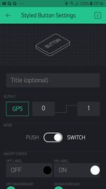
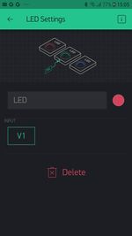
Auf dem Sparkfun-Blynk-ESP8266 Board befindet sich ein Taster, der sich gut dazu eignet, um zum Beispiel den aktuellen Zustand einer Tür (Reed-Schalter) in der App sichtbar zu machen. Dieser Taster ist mit Pin 0 verdrahtet und kann ober einen virtuellen Pin gelesen werden.
Onboard-RGB-LED
- Board: Sparkfun-Blynk-ESP8266
- Onboard-Taster an Pin — kann auch über einen externen Taster zischen Pin 0 und GND geschaltet werden
- Example-Code (siehe unten)
- Example-Blynk-App-Settings (siehe unten)
// Sparkfun-Blynk-ESP8266 Read Onboard-Button Example

/* Comment this out to disable prints and save space */
#define BLYNK_PRINT Serial

#include <ESP8266WiFi.h>
#include <BlynkSimpleEsp8266.h>

// You should get Auth Token in the Blynk App.
// Go to the Project Settings (nut icon).
char auth[] = "YourAuthToken";

// Your WiFi credentials.
// Set password to "" for open networks.
char ssid[] = "YourNetworkName";
char pass[] = "YourPassword";

#define ButtonPin 0

int prevState = -1;
int currState = -1;
long lastChangeTime = 0;

void checkPin()
{
  // Invert state, since button is "Active LOW"
  // int state = !digitalRead(ButtonPin);
  boolean state = !digitalRead(ButtonPin);

  // Debounce mechanism
  long t = millis();
  if (state != prevState) {
    lastChangeTime = t;
  }
  if (t - lastChangeTime > 50) {
    if (state != currState) {
      currState = state;
      if (state == 0) {
        Blynk.virtualWrite(V1, 0);
        Serial.println("Button Off");
      }
      if (state == 1) {
        Blynk.virtualWrite(V1, 1023);
        Serial.println("Button On");
      }
    }
  }
  prevState = state;
}

void setup()
{
  // Debug console
  Serial.begin(9600);

  Blynk.begin(auth, ssid, pass);

  // Make ButtonPin default HIGH, and attach INT to our handler
  pinMode(ButtonPin, INPUT_PULLUP);
}

void loop()
{
  Blynk.run();
  checkPin();
}
Sparkfun-Blynk-ESP8266 Onboard-NeoPixel
Auf dem Sparkfun-Blynk-ESP8266 Board befindet sich eine RGB LED, die sich sehr gut dazu eignet, um zum Beispiel einen aktuellen Zustand anzuzeigen. Diese RGB LED vom Type WS2812 ist mit Pin 4 verdrahtet und kann über die Library Adafruit_NeoPixel.h angesteuert werden.
Onboard-RGB-LED
- Board: Sparkfun-Blynk-ESP8266
- LED-Type: WS2812
- Library: Adafruit_NeoPixel.h
- Pin: 4
- Example-Code (siehe unten)
- Example-Blynk-App-Settings (siehe unten)
// Sparkfun-Blynk-ESP8266 Onboard-NeoPixel Example

#define BLYNK_PRINT Serial
#include <ESP8266WiFi.h>
#include <BlynkSimpleEsp8266.h>
#include <Adafruit_NeoPixel.h>

// You should get Auth Token in the Blynk App.
// Go to the Project Settings (nut icon).
char auth[] = "YourAuthToken";

// Your WiFi credentials.
// Set password to "" for open networks.
char ssid[] = "YourNetworkName";
char pass[] = "YourPassword";

#define PIN 4
int stripR = 0;
int stripG = 0;
int stripB = 0;
int stripL = 0;

Adafruit_NeoPixel strip = Adafruit_NeoPixel(1, PIN, NEO_GRB + NEO_KHZ800);

BLYNK_WRITE(V1)
{
  stripR = param[0].asInt();
  stripG = param[1].asInt();
  stripB = param[2].asInt();
  showRGB();
}

BLYNK_WRITE(V2)
{
  stripL = 255 - param.asInt();
  showRGB();
}

void showRGB() {
  int r = stripR - stripL;
  if (r < 0) r = 0;
  int g = stripG - stripL;
  if (g < 0) g = 0;
  int b = stripB - stripL;
  if (b < 0) b = 0;

  strip.setPixelColor(0, strip.Color(r, g, b));
  strip.show();
}

void setup()
{
  // Debug console
  Serial.begin(9600);
  Blynk.begin(auth, ssid, pass);

  strip.begin();
  strip.show();
}

void loop()
{
  Blynk.run();
}
Sparkfun-Blynk-ESP8266 Onboard-Temp-Humidity Senor
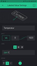
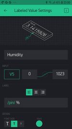
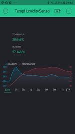
Auf dem Sparkfun-Blynk-ESP8266 Board befindet sich eine Temperatur- und Feuchtigkeitssensor, der sich sehr gut dazu eignet, um zum Beispiel das Raumklima zu erfassen. Diese I2C Sensor vom Type Si7021 ist mit Pin 2 und Pin 14 verdrahtet und kann über die Library SparkFun_Si7021_Breakout_Library.h ausgelesen werden.
Onboard Temperature and Humidity Sensor
- Board: Sparkfun-Blynk-ESP8266
- Sensor-Type: Si7021
- Library: SparkFun_Si7021_Breakout_Library.h
- Pin: 2 & 14 (werden von der Library automatisch gesetzt)
- Example-Code (siehe unten)
- Example-Blynk-App-Settings (siehe unten)
// Sparkfun-Blynk-ESP8266_Onboard-TempHumidity_Example

/* Comment this out to disable prints and save space */
#define BLYNK_PRINT Serial

#include <ESP8266WiFi.h>
#include <BlynkSimpleEsp8266.h>
// #include <DHT.h>
#include "SparkFun_Si7021_Breakout_Library.h"
#include <Wire.h>

// You should get Auth Token in the Blynk App.
// Go to the Project Settings (nut icon).
char auth[] = "YourAuthToken";

// Your WiFi credentials.
// Set password to "" for open networks.
char ssid[] = "YourNetworkName";
char pass[] = "YourPassword";

float humidity = 0;
float tempf = 0;
float tempc = 0;

//Create Instance of HTU21D or SI7021 temp and humidity sensor and MPL3115A2 barrometric sensor
Weather sensor;

BlynkTimer timer;

// This function sends Arduino's up time every second to Virtual Pin (5).
// In the app, Widget's reading frequency should be set to PUSH. This means
// that you define how often to send data to Blynk App.
void sendSensor()
{
  getWeather();
  printInfo();
  sendValues();
}

void setup()
{
  // Debug console
  Serial.begin(9600);

  Blynk.begin(auth, ssid, pass);
  // You can also specify server:
  //Blynk.begin(auth, ssid, pass, "blynk-cloud.com", 80);
  //Blynk.begin(auth, ssid, pass, IPAddress(192,168,1,100), 8080);

  //Initialize the I2C sensors and ping them
  sensor.begin();

  // Setup a function to be called every second
  timer.setInterval(1000L, sendSensor);
}

void loop()
{
  Blynk.run();
  timer.run();
}

//---------------------------------------------------------------
void getWeather()
{
  // Measure Relative Humidity from the HTU21D or Si7021
  humidity = sensor.getRH();

  // Measure Temperature from the HTU21D or Si7021
  // tempf = sensor.getTempF();
  tempc = sensor.getTemp();
  // Temperature is measured every time RH is requested.
  // It is faster, therefore, to read it from previous RH
  // measurement with getTemp() instead with readTemp()
}
//---------------------------------------------------------------
void printInfo()
{
  //This function prints the weather data out to the default Serial Port

  Serial.print("Temp:");
  Serial.print(tempc);
  Serial.print("°C, ");

  Serial.print("Humidity:");
  Serial.print(humidity);
  Serial.println("%");
}

void sendValues() {
  // You can send any value at any time.
  // Please don't send more that 10 values per second.
  Blynk.virtualWrite(V5, humidity);
  Blynk.virtualWrite(V6, tempc);
}
Besonderheiten des Sparkfun-Blynk-ESP8266
BlynkTimer
DeepSleep
low-power operation DeepSleep
Blynk + P5*JS
